
ALMiG Benefits
Speed Control
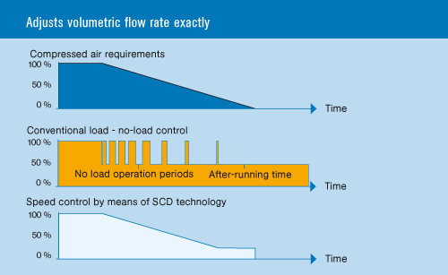
Market analyses show that conventional compressors only operate at approx. 50 - 70% of their capacity and the maximum volume of compressed air delivered (100% capacity load) is only required during peak times. It is precisely this margin, i.e. in applications below full capacity utilization, where the strong points of energy-saving speed-controlled compressors with SCD technology come to bear most. SCD technology stands for speed-controlled direct drive and is a concept that efficiently implements the advantages of SCD speed control combined with an SCD direct drive and a highly efficient, integrated SCD frequency converter.
Average overall costs of a compressed air station:
Energy costs are a major item in a compressed air station. In spite of the fact that energy prices are continuously rising, today up to 40% more energy is being consumed than is really necessary.
One of the causes of this is compressed air produced by standard compressors only with fixed speeds.
Conventional or standard compressors with fixed-speed motors can only cater to the varying air requirements for a specific production if they use load - no-load control or by means of proportional position action orback pressure regulation. However, in both cases there is an enormous loss of output if they are operated at below maximum capacity.
State-of-the-art, intelligent "energy-saving compressors" To compensate for this design disadvantage, "energy-saving compressors" with speed-controlled drives are being used today.
The essential advantages of this concept are the following:
Maximum economic efficiency
- By varying the motor speed, the speed-controlled screw compressors consume only the amount of power that is actually required to produce the quantity of compressed air required.
- Exact adjustment of the volumetric flow rate to the relevant compressed air requirements reduces expensive no-load times to a minimum (no-load means approx. 25 - 30% of the total power consumption of the compressor without any compressed air being produced).
Constant network pressure
Speed-controlled screw compressors hold the input final compression pressure at +/- 0.1 bar constant level within a pressure range, even if the compressed air quantity requirement fluctuates. This facilitates a lower final compression pressure and saves energy.
Free selection of the optimal operating pressure
Speed-controlled compressors make it possible to select the operating pressure freely between 5 and 13 bars in 0.1 bar degrees. Therefore, optimum adjustment to all on-site conditions, e.g. day and night shifts, can be implemented in a matter of seconds. This guarantees maximum flexibility and efficiency across a broad range of applications and in case of future plant extensions.
Energy-conserving start-up without peaks
Furthermore, wth its fully-integrated SCD frequency converter and the innovative and highly efficient SCD motor, a speed-controlled screw compressor is distinguished by the fact that owing to the system the motor starts up gently without causing expensive peaks. Power consumption of the SCD motor at start-up is always lower than the rated current.
Your potential energy savings in figures:
Compared to a standard compressor, using an "energy-saving compressor" with speed control can achieve savings in the following areas:
- Avoidance of no-load running
- Less frequent pressure relief
- Reduced pressure loss (owing to less frequent relief)
- Optimised pressure range (constant network pressure)
- Direct drive (preventing loss of drive)
- Reduced leakage
The following example demonstrates the potential energy saving involved in using speed-controlled compressors.
Example:
- Screw compressor with an installed motor output of 60 kW
- A load ratio of 70%
- 4,000 operating hours p.a.
- 10 bars operating pressure
- Energy costs at 6 cents/kWh.
- Result = €5,400.-
Compressed Air Distribution
According to an EU study ("Compressed Air Systems in the European Union"), in 80% of all enterprises the compressed air distribution systems are the weakest link in compressed air technology. This means that each year thousands of euros are literally blown out of the window for energy costs.
Compressed air distribution has the job of transporting the energy carrier compressed air with as little impact as possible on the air quality (owing to rust, water, welding scale etc.), flow pressure (owing to uneconomical pressure losses) and quantity (owing to unnecessarily large leaks).
Pressure drops cost a lot of money
Each compressed air consumer in the network requires a specific optimal operating pressure. If the operating pressure is too low, e.g. caused by too narrow tube cross sections, the performance of the consumer is disproportionately reduced. By contrast, if pressure is too high it not only pushes energy costs up unnecessarily, it also shortens the service life of the consumers.
Pipeline dimensioning
It goes without saying that the correct dimensioning of the compressed air network has a direct impact on the performance of the compressors, the consumers and hence on the costs of compressed air production.
The most important design criteria for the compressed air network are:
- The volumetric flow rate
- The operating pressure
- The length of the piping
- The drop in pressure
If these criteria are taken into account it is possible to ascertain the correct diameter for the compressed air lines. The pipeline diameter is dimensioned either
- By using standard layout diagrams (monograms) (c.f. Illusory. 1),
- By using standard tables from which the diameters can be read directly (c.f. Illustr. 2) or
- By calculating applying an approximate formula:
The first line, A (pipe length) is connected to line B (intake quantity) and extended to axis 1. Then line E (system pressure) is connected to line G (targeted pressure loss). Finally, the resulting intersections on axes 1 and 2 are connected by a straight line. This straight line cuts across line D; the required internal diameter can be read from this.
As a rule the nominal width of the compressed air line should be big. Some of the greatest losses of pressure occur owing to compressed air lines that are dimensioned too small or rather too narrow. Experience shows that in the case of an originally correctly-dimensioned compressed air network over the course of time an increasing number of consumers is attached to the existing pipeline network with the network having been redimensioned to accommodate new requirements. It is not unusual for just the compressor output to be raised to cover the increased consumption.
The economically acceptable drop in pressure (c.f. Illustr. 3)
With an optimally designed compressed air network the drop in pressure between generation and consumer is subdivided as follows:
- < 0.03 bars for the main pipe (between compressor room/receiver and the main consumer centre)
- < 0.03 bars for the loopline / distributor line (part of pipe that distributed the air within a consumer centre)
- < 0.04 bars for the connection line/branch line (connection between distributor line and consumer)
The pressure loss in the individual components of the compressed air treatment system can be represented as follows:
The amount of the overall pressure loss depends on:
- Degree of contamination and number of treatment components
- Type and number of fittings
- Nominal width of the compressed air piping system
The less auspiciously a compressed air pipe is conceived, the higher the performance of a compressor must be in order to build up the required pressure and maintain it. This means: 1 bar loss in the compressed air system = 1 bar more output on the compressor = approx. 10% higher power consumption.
The influence of piping elements
Each element in a compressed air pipe system, irrespective of whether it concerns treatment elements or pipeline fixtures, cause a pressure loss owing to flow resistances. Taking pressure loss due to fittings into account, in this connection a straight pipeline would be ideal. However, owing to constructional circumstances, as a rule pipelines cannot be laid from the producer to the consumer without fittings.
Changes of direction, for example when circumnavigating supporting pillars, can be avoided by laying the compressed air line next to the obstacle. 90° angles can easily be replaced by large-dimensioned 90° bends (s. Illustr. 5). This makes it possible to reduce the pressure loss to a fraction of the original pressure loss.
In addition to these influences, materials adapted to the various applications must also be used. Factors influencing the use of correct materials include the following:
- Compressed air quality
- Pipe dimensions
- Pressure
- Ambient influences
- Cost of assembly
- Cost of materials
Extending a compressed air line
Another good way of extending the "overrun" compressed air lines is to install a parallel line, which you connect to the existing distributor line. The piping system can hence be extended at no great cost to form a "loopline system".
Leak Reduction
Is your compressed air system still tight?
Analyses confirm that there are leaks in all compressed air stations and enormous quantities of compressed air in which you have invested expensive electrical energy are getting lost on the way from the air compressor to the compressed air consumer. A large number of firms from a variety of industrial sectors have been analyzed in the course of the measuring campaign. The average leakage rate was approximately 25%; the proud "winner" had a leakage rate of around 80%. In other words: of 100 kWh this company was blowing 80kWh back into the atmosphere to no avail whatsoever.
Leaky spots in an overall compressed air system, i.e. in the distributor line or at the various connection points to the consumers represent a high cost factor. The leaky spots act like jets through which the air is expelled at an enormous speed. In view of the fact that air is invisible and odourless and does not represent a direct hazard, it is usually treated with a similar degree of attention as, for example, a leak in a water pipe. The increasing volumetric flow rate requirement caused by the leaks gives rise to higher energy costs for the generation of compressed air.
The following table gives an impression of the extent of energy costs caused by leakage:
As you can see, even a small leakage with a diameter of only 5 mm (total diameter of the whole of many small leaks adding up to 5 mm) in a 12-bar compressed air network has disastrous consequences, i.e. air losses of 58.5 L/s for the generation of which you have to pay over 16,000 € p.a.
The first step towards optimization is to establish the quantity leaking out.
Possible ways of establishing the quantity leaking out
There are various ways of establishing or measuring the quantity leaking out:
1.) Establishing leaks by emptying the compressed air receiver - The quantity leaking out of a compressed air system can be established approximately by emptying the pressure tank. This involves measuring, for example, the period during which the pressure drops by 1 bar. During measuring the tank is no longer supplied with compressed air. Assuming that the compressed air flows out isothermally, the quantity leaking out of a compressed air system can be approximately determined by applying the following formula:
2.) Determining leaks from compressor running times - The second method for roughly determining the quantity of leakage is via the duty cycle of the compressor. This method can be applied to compressors with intermittent and no-load operation only. The consumers in the network are switched off. Owing to leaks in the system compressed air is consumed and the network pressure drops. The compressor has to replace the quantity leaking out. Over a measuring period the total running time T of the compressor is measured. To obtain a representative result, the measuring period t should include several switching intervals of the compressor.
3.) Determining leakage by measuring compressed air consumption - Another method for determining the quantity of leakage is to measure by means of volumetric flow measuring devices (so-called data loggers), which calculate the compressed air consumption profiles of a compressed air station via the load cycles of the compressor. The existing leaks can be deduced from these measuring data / graphs.
Locating leaks
- Soaping the compressed air connections
- Noise development
- Ultrasonic measuring devices
As you can see, in many cases establishing the quantity leaking out and the place leaks are occurring is easy and remedying it relatively cheap, particularly in view of the fact that approx. 70% of compressed air leaks occur in the last 30% of the compressed air system.
Especially weak spots are:
- Leaky quick-release couplings
- Leaky connecting hoses to the respective compressed air consumers
- The use of outdated condensate drains (floating drains, time controlled solenoid valves)
- Outdated compressed air consumers (e.g. Overblowing compressed air tools)
- "Disintegrated" seals on pneumatic control elements and many more
Heat Distribution
The heat recovery of your screw compressor offers you considerable savings potential. Did you know that the energy consumed for producing compressed air is all converted into heat? The heat diagram below shows the amount of heat that arises in oil-injected screw compressors.
Hard facts
A compressed air station with, for example, a required output of 75 kW, consumes approximately 300,000 kWh at 4,000 operating hours per annum. Recover this energy in the form of:
- hot air to support the space heating
- hot water to support, for example, the central heating or process water
How big are your potential savings? Check out the table below to see an overview of the energy saving potential of the compressors depending on the respective installed rated outputs.

Hot air for room heating
The heated cooling air is used to heat a room via a ductwork system. Temperature-controlled valves achieve a regulated, adjustable room temperature. In winter the heat from the exhaust air is used entirely or partly for heating purposes. In the summer it is blown out into the air via an exhaust air channel.
Hot water for heating purposes
Plate heat exchangers are used to produce hot water. The heating water runs through "plates" within a closed housing. The hot compressor oil flows between plates and housing and delivers its heating power to the hot water.
Heat for service and process water
The heat recovery process is the same as for heating water. Shell-and-tube heat exchangers are used to prevent oil from penetrating the service water even if there are leaks.
Three alternative ways of saving money!
Integrated heat recovery
All components required for heat recovery are installed in the compressor during the production process.
Advantage:
- Simply connect up in the building and immediately start saving cash!
- Constant temperature regulation: Depending on the available heat, the water temperature on the customer's side will be kept at the desired temperature level.
Preparation for heat recovery
If the order is for a new compressor, it will be prepared for heat recovery, i.e.:
- ball valves on the oil tank outlet
- The space needed for heat exchangers etc. has been allowed for in the plant.
- The apertures for the connections have already been pre-drilled into the panelling.
- It can be completed at no expense at a later date by using a retrofitting set (Heat exchanger, control valve + temperature sensor, and hose connector/pipe coupling)
Heat recovery for (old) compressors previously installed
External modules for retrofitting previously installed compressors.
Advantage:
- Easy to connect to all compressors
- Fully equipped with all the necessary, highly efficient components and safety devices
- Minimal installation costs thanks to the intelligent ALMiG design
- Constant temperature regulation

*Effective volume of usable heat at 75 % heating efficiency
** Speed-controlled compressors: Values refer to an average 70 % capacity utilisation.